Brompton Factory

Behind the scenes with Brompton

Having ridden in the Brompton World Championships in 2016 and again at the weekend in the 2017 final, I had the opportunity this week to take a tour around Brompton’s factory in London.

The tour begins with an overview of the company’s history, starting in 1975 when Andrew Ritchie first had his idea for a folding bicycle and over the next seven years he built various prototypes.

Brompton Museum Factory
An Original Design Brompton

By 1981 the design had improved and featured a bent main frame tube and main hinge assembly, fifty of these pre-production models were sold in order to raise capital after several appeals to banks and bike companies were turned down.  Most notably was this decision from Raleigh in 1982.

Letter to Andrew Ritchie from Raleigh Bicycles
1982 Letter from Raleigh

Little did they know then that they were rejecting a company that is now a classic icon for British design, engineering and manufacturing which can produce almost a thousand handmade bicycles a week.

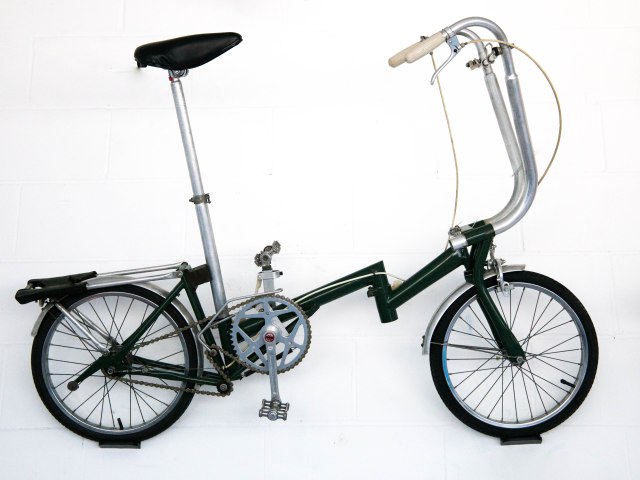
Production of the mark 1 commenced in 1982, the receipt for bicycle number 229 had a selling price of £239 (approx £755 in todays value).

Brompton Museum Factory
Mark 1 Brompton

Production halted in the mid-eighties until Julian Vereker, a Brompton enthusiast and friend of Andrew’s invested in the company.  Production restarted in 1986 and by 1987 the company moved to its first factory under a railway arch in Brentford. The new factory allowed full production of the mark 2 to start with the first bikes being delivered in 1988.

Brompton Museum Factory
1988 Mark 2

In 1993, due to an ever expanding business, production was moved from the railway arches to Bollo Lane a couple of miles away. Just five years later (1998) this new space was once again too small to meet the demands of production and the factory moved back to Brentford, which would be home to Brompton for the next 18 years.

Towards the end of 2016 the company moved to it’s new premises and on the 28th November 2016, HRH The Duke of Edinburgh officially opened the new factory in Greenford.

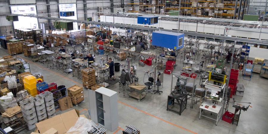
The majority of the building is taken up with the main production processes, but it also houses the entire Brompton business from administration, R&D, after sales support, parts, etc.  The tour covered the production processes and therefore the three main areas, pre-production, paint, and final assembly.

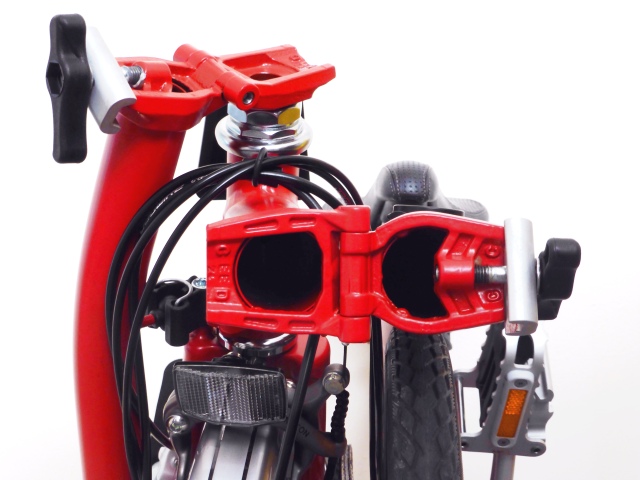
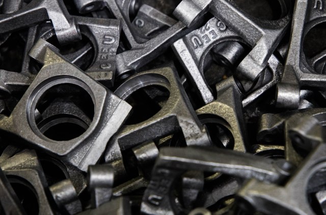
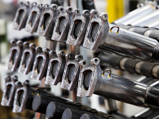
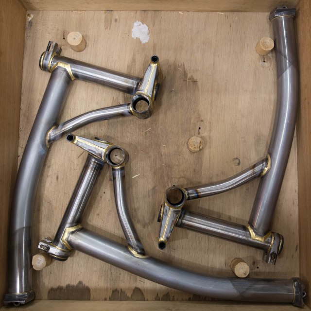
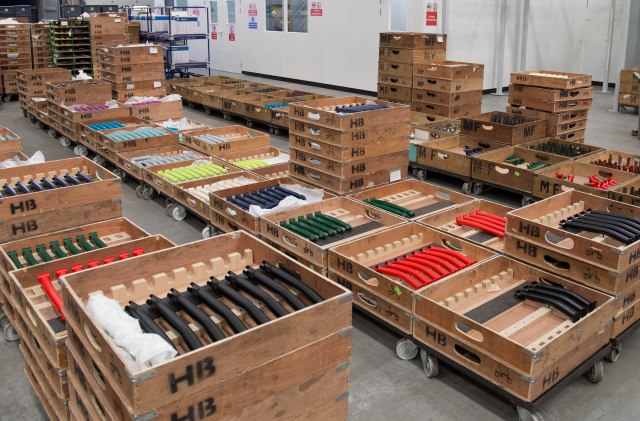
It seems rather fitting that every Brompton folding bike starts with the two hinge assemblies, the main tube and the handle bar support.

Brompton Handlebar Support Hinges
Brompton Hinges

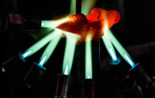
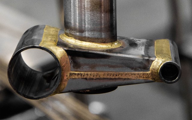
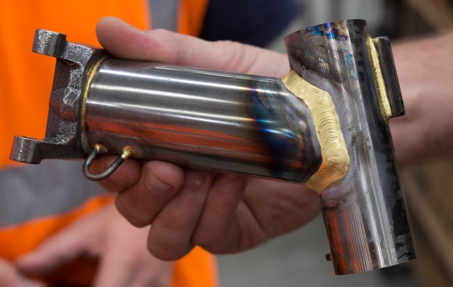
The hinge plates are brazed onto the tubes using a machine to ensure the strongest possible bond, every other join on the bike is brazed by hand. Brazing is the process of joining two or more pieces of metal together using another metal as a filler that has a lower melting point than the pieces being joined.  It differs from welding where the pieces being joined are melted in order to bond together.

Brompton bikes are made from steel, with brass as the filler.

Brompton Hinge being forge welded onto the handlebar support
Brompton Hinge being brazed onto the handlebar support
Brompton Main Frame Tubes
Brazed and cleaned Brompton main frame tubes
Brompton Main Hinge Assembly
Handlebar Support Tubes

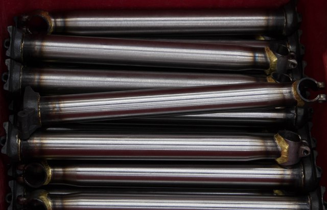
The next, and probably the most important, step is to bend the main tube to form the iconic curved main frame tube, without it, it just wouldn’t be a Brompton.

Every single Brompton main tube since 1988 has been formed using this machine, in a process that takes just seconds.

The handle bar support tubes are also bent to a specific shape depending on the type of bars that will be fitted to the bike. With the tubes complete, the process of brazing the frames can start. Rather than have one person braze every joint on a single bike, the process is broken down into several steps, each focussing on a separate component. For example, Main Frame, Bottom Bracket, Head Tube, Rear Triangle etc.

Brazing the Brompton Main Frame Assembly
Brazing the Brompton Main Frame Tube Assembly
Brompton bottom bracket
Newly assembled / brazed Brompton main frames
Rear Triangle Assembly
Head Tube
Head Tube

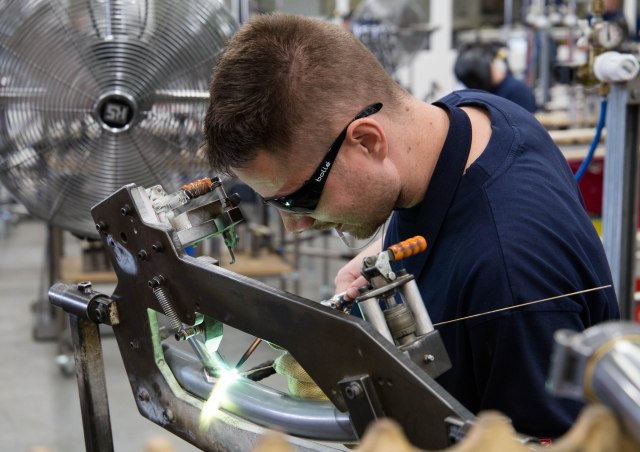
The highly skilled braziers are trained on each component and rotate around the processes, generally doing two different components each day. There are hourly targets for each component, i.e. for the main frame assembly the brazier should be completing 15.3 frames a hour.

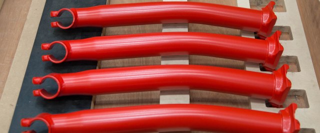
Once all the components have been brazed they are sent to the paint shop for powder coating.

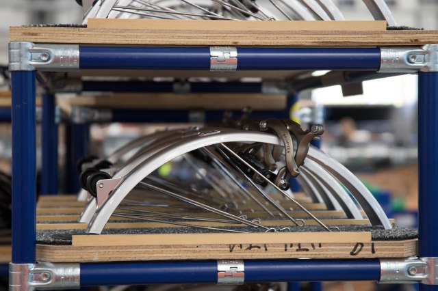
The central part of the factory contains the parts department, they process all orders for spare parts from dealers, bike shops and consumers from around the world.

Individual components are also assembled in this area, these are put together based on the current demand.  Today they were assembling mudguards, brake callipers and reflectors.

Component assembly
Component assembly – Rear mudguard and brake calliper.

Unfortunately we didn’t get to see the powder coating process in action, as they were in the middle of a colour change, this generally happens about 4 times a week.

Although the process had started, the frames and components go through a five step process from cleaning, the powder being hand sprayed on to finally being baked at 180 degrees celsius for 10 minutes.  The heating and cooling process is carefully controlled and monitored to ensure an even paint finish and that the metals do not deform.

Frame Assemblies Ready For Paint
Freshly painted Brompton handlebar supports
Pick a colour! Brompton components fresh from the paint plant.

With all the frames painted and sub-components put together the final assembly of the bike we all know and love can start. This is done on two identical assembly lines, each consisting of seventeen bays.

Brompton Assembly Line

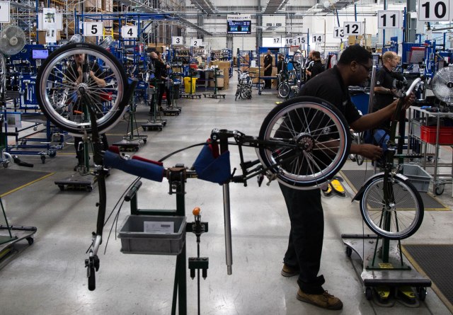
As you expect the assembly starts at bay one where the main frame and head tube hinge plates are joined together, bottom bracket inserted and the seat post clamp is fitted.

Special edition Brompton frames and head tubes.
Brompton Frames after the first stage of assembly

Next the seat post is fitted and the bike is mounted onto a trolley so that it can be easily moved between the bays.

Every bike has a “Pink Slip” (originally printed on pink paper, changed to standard white to save costs, but the name’s stuck). This slip tells the worker what type of Brompton it is and what components need to be fitted to it.  It also contains all the information about the bike, serial number, order number, customer etc.

Pink Slip – Order Details
Brompton Assembly Line
Assembly Line

From here the bike is passed from bay to bay until at bay 17 the fully assembled bike is checked and packaged ready to be shipped to the customer.

The end of the line
The end of the line

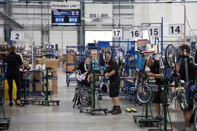
Screens at each end of the production line show the current progress. At the time of the visit (11.17am) the screen shows that 58 bikes have been built today at a rate of 15 bikes an hour (target 14).  At full capacity both lines can build almost 1000 bikes a week.

Boxed Bromptons
Boxed and ready for the customer

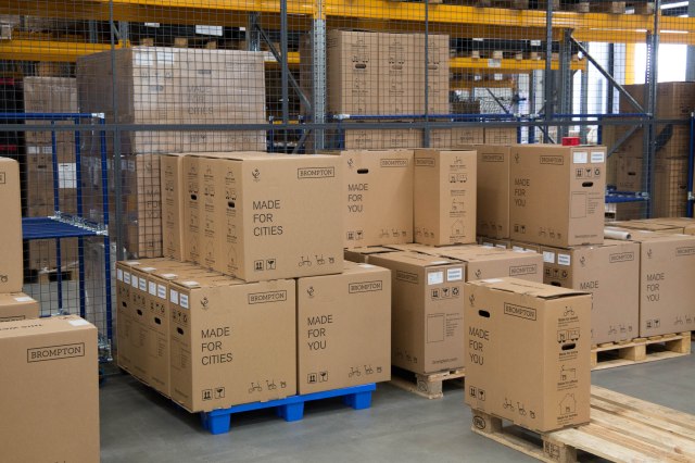
The final step once packaged is to load the boxes onto pallets for distribution to the customers.  I wonder how many of the bikes (and their proud new owners) I saw being built today will race around St James’s Park in London this time next year in the Brompton World Championship Final 2018.

Folded Brompton
My Brompton straight from the Brentford factory on the day of delivery back in 2014
Ordnance Survey Flying Unit

Above the scenes with Ordnance Survey

Back in February I went behind the scenes at Ordnance Survey with Dom Turnor, a Field Surveyor at OS, to find out how the master map of Great Britain is updated. During the day I discovered that there are areas that cannot easily be surveyed on the ground, this can be for a variety of reasons including the size/nature of the site, access restrictions or the safety of the surveyor. In these situations the changes can be surveyed using aerial photography. Ordnance Survey have had a dedicated Flying Unit since 1966. OS used aerial photography prior to this and had operators of it’s own, however it was shared with the Royal Air Force and other government departments.

I met up with Air Camera Operator and Field Surveyor Roger Nock at East Midlands Airport to find out more about the Flying Unit and how they capture the aerial imagery required to update the master map.

Ordnance Survey Cessna 404 / G-FIFA

Ordnance Survey have several planes, each equipped with a large format digital aerial camera system by Vexcel Imaging. This is a state of the art UltraCam digital camera, consisting of eight lenses and 196 megapixels.

The camera/sensor unit is mounted behind the camera operators seat with the airborne computing unit, removable data storage and interface panel to the operators left. The pilot has a secondary display screen which can be mounted to the instrument panel whilst imagery is being captured.

G-TASK Inside

IMG_5628-2

Mounted in front of the camera operator is a forward looking scope for a detailed view of the area and terrain ahead of the aircraft.

Image through the Air Camera Operators scope - Photo by Ordnance Survey
Image taken through the Air Camera Operators scope – Photo by Roger Nock / Ordnance Survey

The flying season is between late February and early November and is very much dependent on the weather, air traffic control and permission to enter areas of restricted airspace.

Not only do they have to factor in the infamous UK weather, our airspace is also one of the busiest in the Europe, if not the world, especially in the South East with the shear volume of arrivals and departures into the main London airports. In 2014, London Heathrow handled 73.4 million passengers during 470,695 aircraft movements, an average of 1290 flights a day (data from LHR Airports Ltd).

Everything needs to be in place for a flight to take place. The weather needs to be favourable, rain and clouds in the target area will cast shadows on the imagery or completely obscure the ground. Permissions from multiple air traffic controllers along the flightpath and permissions to enter restricted flight areas need to be obtained, the pilots total flying hours that day also needs to be considered, not just total flown so far but the planned flying hours for the sortie need to be taken into consideration and of course the serviceability of the aircraft itself. However, before any of this can take place the flight needs to be planned, which starts with a request for a target to be flown. These can come from various sources including, field surveyors, OS HQ etc.

One target request that needed planning whilst I was visiting was for the Glaslyn river estuary in North Wales, this estuary is predominately sand banks and needs to be accurately surveyed in order to update the master map. As you can imagine this task just isn’t feasible for a ground field surveyor to undertake.

Afon Glaslyn / Traeth Mawr
Afon Glaslyn Estuary – Crown Copyright Ordnance Survey

With the target site identified, the air camera operator checks the Civil Aviation Authority (CAA) airspace charts for the location and any flying restrictions/hazardous areas.  The majority of North Wales is free airspace, however there a few restricted areas with an RAF airfield on Anglesey and some of the valleys being used for low level fast jet training. In our case the Glaslyn estuary is in the free airspace, so there are no restrictions or additional permissions required.

Flight Planning in the OS Flying Unit

Aerial imagery is captured by flying at a set speed and altitude in a straight line with a photo being taken approximately every 3 seconds (depending on speed).

Having entered certain details into the computer, such as Camera Type, Ground Sample Distance (GSD is the distance between the pixels on the image measured on the ground eg. in an image with a one metre GSD, adjacent pixels image locations are 1 metre apart on the ground).

The operator can then draw the flying strips onto the target area, these appear as black rectangles with the blue centre line being the flightpath of the aircraft and the red dots indicate the location an image will be captured. In order to obtain the best quality survey the images are overlapped, generally by 30%. Additional strips are added until the target area is completely covered as shown in the screenshot below.

Whilst the location of each photo is captured with GPS it is good practice to include several map features in the imagery, such as a main road or village centre, so that the newly acquired imagery can be aligned with existing map data. The original target area is the black outlined polygon just visible under the main rectangles.

OS Flight Planning

In order to fully survey the estuary OS will need to fly five lines capturing a total of 144 images, with each line being flown at 5,800 feet and 175 knots. This relatively small target area will take approximately 30 to 35 minutes to survey when you add in the time it takes to turn the plane at the end of each line. In this example the altitude of each line remains constant as the terrain is flat, in more hilly areas the altitude of each line needs to be adjusted in line with the terrain so that the GSD remains constant as well. An additional element for this sortie is that it must be flown at low tide thereby adding to the complex of scheduling it.

The weather had been poor in the morning of my visit and just when it was looking like we wouldn’t get to fly at all, there was a break in the weather over South Wales and we would be able to fly a sortie. The selected target in Aberporth was a single line which would take five minutes to survey at an altitude of 5800 feet.  During the week the area is restricted airspace and even though it was a Saturday permission would still be required to fly in the area.

Aberporth Flying Danger Zone
CAA Airchart / Aberporth Danger Zone – Crown Copyright Ordnance Survey

Our pilot for the day Liam Watt had called ahead and with permission granted, the surveying systems setup and configured we took to the skies over East Midlands and set course for Cardigan.

IMG_7747

The outbound flight took us out towards Ironbridge, south of the Wrekin and then over the Shropshire Hills and the Welsh Marches.

IMG_7780
Outbound flight over Ironbridge, Shropshire

IMG_7782

We had to be extra vigilant in this area by keeping an eye out for gliders, due to the number of clubs in the area and the weather was perfect for the gliders to soar on the thermals, their small size makes them difficult to see.

Long Mynd Gliding Club
Midland Gliding Club, Long Mynd – Photo by Roger Nock
IMG_7794
Banking over the Welsh Coast approaching the target line

As we approached the target area, I heard Liam say to Roger over the intercom  “cloud on the line”, this potentially meant we would have to abort the sortie and return to East Midlands without any images. Fortunately as we turned for the line it was in fact clear and Roger started capturing the imagery.

From the co-pilots seat I watched Liam’s secondary screen on the instrument panel in front of me.  The images below shows: Top Left – approaching the line.  Right – flying the line. Bottom Left – Line complete and turning back for East Midlands.

Flying the Line

Roger Nock - Line Complete

Roger was happy with the images he captured and with the survey complete we turned for the return flight over the Welsh Marches and the Shropshire Hills back to East Midlands airport.

IMG_7802

Landing at East Midlands
Ordnance Survey Cessna 402 - G-NOSE
Ordnance Survey Cessna 402 – G-NOSE

Having landed and taxied back to the hanger, the last remaining tasks are to remove the data storage units from the aircraft and copy the imagery from the aircraft systems onto the servers where they will be sent to OS in Southampton for processing and updates to the master map will be made.

I would like to thank Ordnance Survey and especially Roger and Liam for giving me access to the Flying Unit for what was a fantastic experience and truly a once in a lifetime opportunity.

Behind the scenes with Ordnance Survey

It’s a practice that has taken place for over a century, people across Great Britain have grabbed Ordnance Survey (OS) maps, unfolded them and then scanned across the beloved grid squares searching out the familiar symbols we all learnt in school – roads, rivers, woods, churches, youth hostels, trig points, train stations, parking, contour lines etc.

All of this detail is vital to help you plan your next adventure and to navigate on the day – Where are you going to park? What feature are you going to take a bearing off? Where might you stop for a spot of lunch?

Ordnance Survey Explorer Map
Ordnance Survey Explorer Map of Great Malvern with the familiar symbols

Have you ever stopped to think about how all this detail gets onto the map in the first place and more importantly how does it get updated?  I spent a day and a half with Dom Turnor, a Surveyor with the OS, finding out how the master map of Great Britain is updated and how often.  I make no apologies for the length of this post as I believe it is deserved given the subject matter and the privileged access given to me by OS.

Dom is one of approximately 250 field surveyors across the country and is responsible for the Malvern District, which is part of the Wales and West Central region.  His district is long and thin from the county borders of Worcestershire and Shropshire in the north, down to Cheltenham in the south, as highlighted in the image below.

Malvern District - Wales and West Central
Malvern District – Wales and West Central showing Land Registry Customer Orders

Due to the size and shape of the District, Dom plans his work into economic packages, saving time, fuel and the environment.  I joined him for this planning on Monday afternoon at his home office where he explained the systems, processes and different types of surveying tasks he undertakes on a daily basis.

You may be surprised to learn that OS make approximately 10,000 changes to the master map every day and aim to capture all major change within 6 months of it happening. Each of these changes start as a field customer order which are generated from numerous sources such as HM Land Registry, Local Councils, Surveyors, OS HQ, third party suppliers etc.  Whilst there are multiple categories for these orders the majority will fall into one of four categories: –

  • Prestige sites – Sporting venues, Large shopping centres.
  • Land Registry – Survey requisitions for boundaries and land access
  • Total Revision – Changes such as construction works, house building
  • Derived Products – The symbols identifying locations and services

The field customer orders are downloaded on a regular basis to the surveyors computer and then “taken-up” to show that a surveyor is assigned to the order. As I would be spending the following day with Dom, he had selected a range of orders from the various categories, with the exception of the Prestige Sites as these are generally complex by nature.  For example the redevelopment of the racecourse in Cheltenham took several full days to survey.

Our customer orders for the following day were: –

  1. Land Registry –  boundary survey between two private properties requested by HM Land Registry so that the deeds to the properties could be updated.
  2. Total Revision – a new Sainsbury’s Local supermarket has recently been built and opened in Malvern.  The store and surrounding area needs to be surveyed and added to the master map.
  3. Land Registry – query over the precise location and boundaries of an electric sub station in Malvern.
  4. Total Revision – several new housing estates and notifications of potential building works in the Malvern area.  These would be initial visits to ascertain the stage of the building works, if any.
  5. Derived Products – a selection of locations and services that we would check were still there as we were passing them.

I met Dom on the Tuesday morning and after a few admin tasks we set off for the first land registry job, as it relates to private property I won’t go into much detail, albeit to say that we met the land owners, surveyed the fence line and boundary identified in the request, along with several photographs from requested viewpoints.

With the land registry job complete, we headed off for the new Sainsbury’s Local in Buttercup Walk, Malvern.

Sainsbury's Local Malvern
New Sainsbury’s Local, 30 Buttercup Walk, Malvern, WR14 1NR

I was surprised and delighted when Dom said that he would let me survey the store! As you can see from the photo above, the store is essentially a rectangular box, with a car park, several fences and landscaped areas.

With the wide open space this is an ideal area to use GPS, the Global Positioning System – a network of satellites in a precise orbit constantly transmitting signals to Earth.  Essentially a GPS receiver compares the time a signal was transmitted by a satellite with the time it is received, it is this time difference between the signals that tells the GPS receiver how far away the satellite is.  Once the receiver picks up more than three signals it can start to triangulate its position, the more satellites it picks up the more precise the location will be. The OS has a beginners guide to GPS if you would like more detail.

Most of us are probably familiar with GPS receivers and have used one in some form or another, with receivers in sat navs, smartphones, activity tracking devices and handheld navigation devices. These devices are generally accurate to within 5 to 10 metres 95% of the time.  Whilst this level of accuracy is sufficient for consumer use, it is not precise enough for detailed mapping. Therefore, each OS Surveyor has a state of the art Leica GS15 GPS receiver, mounted on a 1.8 metre pole and connected to the surveyors laptop via bluetooth and to the cellular phone network.

Surveying with the Panasonic Toughbook computer and Leica GS15 GPS Receiver
Surveying in Malvern with the Panasonic Toughbook laptop and a Leica GS15 GPS Receiver

With the equipment setup and connected Dom handed it over to me, I planted the GPS pole on the first corner of the car park, ensured it was level, waited for it to acquire the satellites (we managed to receive signals from 14 satellites), I watched the accuracy/quality of the signal improve to 0.01 (I believe that means an accuracy of 1cm!) and clicked on measure.  A dot appeared at our location on the map, we moved on to the next corner, waited for the accuracy to be less than 0.10, click another dot, then a line appeared joining the dots, move to the next corner, click, another dot, and so on until we had the complete outline of the car park.  Next came the curved kerbs of the entrance to the car park, selecting the curved line tool I measured several points around the kerbs.  Next up was the fencing and footpaths around the site.  With all the landscaping and ground work complete it was time to survey and plot the buildings location.

To get an accurate location with GPS the receiver needs a clear view of the sky, up until this point we were getting very accurate measurements, as we went closer to the walls of the building the accuracy dropped to an unacceptable level.  Therefore to obtain the locations of each corner, we measured a point along the line of each wall, as close as possible with an acceptable accuracy level.  When you have six of these measurements (two at each of three corners) you can join the survey points with lines (the same as plotting the kerb line of the car park), these lines will intersect at each of the four corners giving you the outline of the building. At this point we had a complete plan of the area made up of multiple polygons on the map.

The next stage is to attribute each of these polygons to define what it actually is, this does not need to be done on site.  As it was approaching midday, we decided on an early working lunch somewhere in the warm.

With a steak and stilton baguette in hand and a warming mug of coffee, we fired up the laptop and started to attribute the polygons we had plotted.  This is where detail is important, for example a path isn’t the same as a pavement (a pavement is on the side of the road, whereas a path goes through an open area), next is the surface sealed or unsealed? likewise a verge can only be used for the side of a public road and not the edge of a car park.  The last attribute to assign is to set the Sainsbury’s building as a functional site (retail) and add the road number to it.  The number on the building must be aligned to the road it is on. The image below shows the final result of our survey.

OS GIS Software - Surveying
OS GIS Software – Surveying and adding Sainsbury’s to the master map

Having eaten and warmed up, with went off in search of the Old Hollow electrical sub station.  The sub station is located up a small dirt track surrounded by tall trees, we attempted to get a GPS location, but as expected the accuracy was out by over three metres due to the trees. Without GPS it was back to the trusty tape measure, line of sight and measuring from other features already plotted on the map.

Old Hollow Electrical Sub Station, Malvern
Old Hollow Electrical Sub Station, a 6.2m square fenced off enclosure in amongst the trees.

Next on our list were several sites that have been marked for new construction works.  There were no signs of any work on any of these three sites. However, this isn’t unusual as planning permission can be granted but the developers do not necessarily start immediately.  Although we did locate two new housing estates being built in Welland. It is important to keep on top of these sites, especially new housing estates as it is quicker and easier to survey a buildings foundation with accurate GPS signals before the walls are built.

Last on the list were several Derived Products, these are the familiar symbols across the map, we didn’t get the opportunity to check many of these as surveying the sub station took longer than expected. A viewpoint, such as the Worcestershire Beacon on top of the Malvern Hills, is extremely unlikely to change.  However, items such as telephone boxes are being decommissioned and removed on a regular basis.  Although most are removed they are also being re-roled for other purposes, such as housing defibrillators or in the case of one in Malvern, a library/book exchange.  Therefore just driving past a telephone box isn’t enough to check that it is still in use.

Having finished the field surveying, we returned to Dom’s house to fill out the paperwork for the land registry surveys, upload our changes to the main OS servers in Southampton and submit the completed field customers orders and paperwork.

I’m now going to be checking the online OS Maps and iPhone OS Maps app daily looking for these changes to appear.  I can now officially say “I’ve put Sainsbury’s on the map”

I can’t thank Dom and the Ordnance Survey enough for showing me a peek behind the scenes, there is so much more detail that I could have added but I wanted to keep it to an overview of the day. I hope that this post gives you an insight into the role of a OS Surveyor and that you found it as informative and enjoyable as I have researching it and writing it.

I am now wishing that I asked to do this for work experience back at school and a pursued a full time career as a Surveyor…